The multimeter uses a reciprocal counting technique to measure frequency and period. This method generates constant measurement resolution for any input frequency. The multimeter's AC voltage measurement section performs input signal conditioning. All frequency counters are susceptible to errors when measuring low–voltage, low–frequency signals. The effects of both internal noise and external noise pickup are critical when measuring "slow" signals. The error is inversely proportional to frequency. Measurement errors also occur if you attempt to measure the frequency (or period) of an input following a DC offset voltage change. You must allow the multimeter's input DC blocking capacitor to fully settle before making frequency measurements.
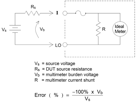
When you connect the multimeter in series with a test circuit to measure current, a measurement error is introduced. The error is caused by the multimeter's series burden voltage. A voltage is developed across the wiring resistance and current shunt resistance of the multimeter, as shown below.
If signal inputs are applied to terminals not needed for the current measurement, measurement errors may occur. The unused terminals are still protected but the un-needed signals may interfere with current measurement. For example, applying inputs to the 3A terminals while making measurements on the 10A terminals will typically cause errors.
The Hi and Lo sense terminals are not used for many measurements. Applying signals here when not needed can also cause errors. AC or DC voltages above 15 volts peak on the un-needed sense terminals are likely to cause measurement errors. If unexpected errors are occurring, signals on the un-needed terminals is an area to check.
Temperature measurements require a temperature transducer probe. The supported probes are 2-wire and 4-wire RTDs, 2-wire and 4-wire thermistors (5 k 44007 type, see Thermistor Requirements below), and, for the 34465A/70A only, type E, J, K, N, R, or T thermocouples.
RTD's provide very accurate, highly linear relationships between resistance and temperature, over a range of roughly –200 to 500 °C. There is very little conversion complexity for an RTD because it is so intrinsically linear. The multimeter provides measurement for the IEC751 standard RTD, which has a sensitivity of 0.385%/°C.
Thermistors consist of semiconductor materials, and provide roughly ten times the sensitivity of the RTD. Because they are semiconductors, their temperature range is more limited, commonly to –80 to 150 °C. Thermistors have highly non–linear temperature–resistance relationships; therefore their conversion algorithms are more complex. The Truevolt Series multimeters use the standard Hart–Steinhart Approximation to provide accurate conversions, with a typical resolution of .08 °C.
The DMM converts the measured thermistor resistance to temperature using the Steinhart-Hart thermistor equation:
1⁄T = A + B (Ln(R)) + C (Ln(R))3
Where:
A, B, and C are constants provided by the thermistor manufacturer and derived from three temperature test points.
R = Thermistor resistance in Ω.
T = Temperature in degrees K.
Important: Use only a 5 kΩ 44007-type thermistor. This type thermistor has constants of A = 1.285e-3, B = 2.362e-4, C = 9.285e-8. Using an incorrect type of thermistor can result in errors greater than 20 °C for a temperature being measured of 100 °C.
For a detailed tutorial on temperature measurements, refer to Keysight Application Note 290 Practical Temperature Measurements available at www.keysight.com.
As with resistance measurements, four-wire temperature measurements are more accurate, because errors due to lead wire resistance are completely eliminated. Alternately, you can use the multimeter’s Null function to remove the test lead resistance from the measurement (see NULL Reading below).
The DMM allows a separate null setting to be saved for the temperature function. When making null measurements, each reading is the difference between a stored null value and the input signal. One application of NULL is to increase accuracy of two-wire resistance measurements by first nulling the closed–circuit test lead resistance.
Enabling the autozero feature (ON) provides greater accuracy; however, the additional measurement (of zero) reduces the reading speed.